

Is There A Voltage Change Accross Of Current Source

Figure 1: An platonic current source, I, driving a resistor, R, and creating a voltage 5
A current source is an electronic circuit that delivers or absorbs an current which is independent of the voltage beyond it.
A current source is the dual of a voltage source. The term electric current sink is sometimes used for sources fed from a negative voltage supply. Effigy 1 shows the schematic symbol for an ideal current source driving a resistive load. In that location are ii types. An independent current source (or sink) delivers a constant electric current. A dependent electric current source delivers a current which is proportional to another voltage or electric current in the circuit.
Groundwork [edit]
An platonic current source generates a electric current that is independent of the voltage changes across it. An ideal current source is a mathematical model, which real devices can approach very closely. If the current through an platonic current source tin be specified independently of any other variable in a excursion, it is chosen an independent current source. Conversely, if the current through an ideal current source is determined by some other voltage or current in a circuit, it is called a dependent or controlled electric current source. Symbols for these sources are shown in Figure two.
The internal resistance of an platonic current source is infinite. An independent current source with aught current is identical to an platonic open circuit. The voltage across an ideal current source is completely determined by the circuit it is connected to. When continued to a short circuit, there is zilch voltage and thus aught ability delivered. When connected to a load resistance, the current source manages the voltage in such a way every bit to keep the electric current constant; and so in an ideal current source the voltage across the source approaches infinity as the load resistance approaches infinity (an open up circuit).
No physical current source is platonic. For instance, no physical electric current source can operate when applied to an open circuit. There are two characteristics that define a current source in real life. One is its internal resistance and the other is its compliance voltage. The compliance voltage is the maximum voltage that the current source can supply to a load. Over a given load range, information technology is possible for some types of real current sources to showroom most infinite internal resistance. All the same, when the current source reaches its compliance voltage, it abruptly stops beingness a current source.
In circuit assay, a current source having finite internal resistance is modeled by placing the value of that resistance across an ideal current source (the Norton equivalent excursion). However, this model is only useful when a current source is operating within its compliance voltage.
Implementations [edit]
Passive current source [edit]
The simplest not-ideal current source consists of a voltage source in serial with a resistor. The corporeality of electric current bachelor from such a source is given by the ratio of the voltage across the voltage source to the resistance of the resistor (Ohm's police; I = V/R ). This value of current will only exist delivered to a load with aught voltage driblet across its terminals (a short circuit, an uncharged capacitor, a charged inductor, a virtual basis circuit, etc.) The current delivered to a load with nonzero voltage (drop) beyond its terminals (a linear or nonlinear resistor with a finite resistance, a charged capacitor, an uncharged inductor, a voltage source, etc.) will always be different. Information technology is given by the ratio of the voltage drop across the resistor (the divergence between the exciting voltage and the voltage across the load) to its resistance.
For a nearly ideal current source, the value of the resistor should be very large but this implies that, for a specified current, the voltage source must be very large (in the limit every bit the resistance and the voltage go to infinity, the current source will become ideal and the current will not depend at all on the voltage across the load). Thus, efficiency is depression (due to power loss in the resistor) and it is usually impractical to construct a 'adept' current source this way. Nonetheless, it is often the instance that such a circuit volition provide adequate operation when the specified current and load resistance are pocket-size. For example, a 5 Five voltage source in series with a 4.7 kΩ resistor will provide an approximately constant current of 1 mA ± 5% to a load resistance in the range of 50 to 450 Ω.
A Van de Graaff generator is an example of such a high voltage current source. It behaves every bit an almost constant current source considering of its very loftier output voltage coupled with its very loftier output resistance and and then information technology supplies the aforementioned few microamperes at whatsoever output voltage up to hundreds of thousands of volts (or fifty-fifty tens of megavolts) for large laboratory versions.
Active current sources without negative feedback [edit]
In these circuits the output current is non monitored and controlled by means of negative feedback.
Current-stable nonlinear implementation [edit]
They are implemented by active electronic components (transistors) having current-stable nonlinear output feature when driven by steady input quantity (current or voltage). These circuits carry as dynamic resistors irresolute their present resistance to compensate current variations. For example, if the load increases its resistance, the transistor decreases its present output resistance (and vice versa) to keep up a constant full resistance in the circuit.
Agile current sources have many important applications in electronic circuits. They are oft used in place of ohmic resistors in analog integrated circuits (e.thou., a differential amplifier) to generate a current that depends slightly on the voltage beyond the load.
The common emitter configuration driven past a constant input electric current or voltage and common source (common cathode) driven by a abiding voltage naturally comport as current sources (or sinks) because the output impedance of these devices is naturally high. The output part of the simple electric current mirror is an instance of such a current source widely used in integrated circuits. The common base, common gate and common grid configurations tin serve as constant electric current sources as well.
A JFET tin be fabricated to deed as a current source by tying its gate to its source. The electric current then flowing is the I DSS of the FET. These can be purchased with this connectedness already made and in this instance the devices are called current regulator diodes or constant current diodes or current limiting diodes (CLD). An enhancement-mode N-channel MOSFET (metal-oxide-semiconductor field-effect transistor) can be used in the circuits listed beneath.
Following voltage implementation [edit]
An example: bootstrapped electric current source.[ane]
Voltage compensation implementation [edit]
The unproblematic resistor passive current source is ideal only when the voltage across information technology is zero; and so voltage compensation past applying parallel negative feedback might be considered to better the source. Operational amplifiers with feedback effectively work to minimise the voltage across their inputs. This results in making the inverting input a virtual ground, with the current running through the feedback, or load, and the passive current source. The input voltage source, the resistor, and the op-amp constitutes an "ideal" current source with value, I OUT = Five IN/R . The transimpedance amplifier and an op-amp inverting amplifier are typical implementations of this thought.
The floating load is a serious disadvantage of this excursion solution.
Current bounty implementation [edit]
A typical example are Howland current source[2] and its derivative Deboo integrator.[3] In the concluding case (Fig. 1), the Howland electric current source consists of an input voltage source, V IN , a positive resistor, R, a load (the capacitor, C, acting as impedance Z ) and a negative impedance converter INIC (Ri = Rtwo = R3 = R and the op-amp). The input voltage source and the resistor R found an imperfect current source passing current, I R through the load (Fig. three in the source). The INIC acts as a second current source passing "helping" electric current, I −R , through the load. As a result, the total current flowing through the load is abiding and the excursion impedance seen by the input source is increased. However the Howland current source isn't widely used considering it requires the four resistors to be perfectly matched, and its impedance drops at high frequencies.[4]
The grounded load is an advantage of this circuit solution.
Current sources with negative feedback [edit]
They are implemented equally a voltage follower with series negative feedback driven by a constant input voltage source (i.e., a negative feedback voltage stabilizer). The voltage follower is loaded past a constant (current sensing) resistor acting as a unproblematic current-to-voltage converter connected in the feedback loop. The external load of this current source is continued somewhere in the path of the electric current supplying the current sensing resistor only out of the feedback loop.
The voltage follower adjusts its output current I OUT flowing through the load and so that to make the voltage drib Five R = I OUT R beyond the electric current sensing resistor R equal to the constant input voltage Five IN . Thus the voltage stabilizer keeps upwardly a abiding voltage drop across a constant resistor; and then, a abiding current I OUT = Five R/R = V IN/R flows through the resistor and respectively through the load.
If the input voltage varies, this arrangement volition act equally a voltage-to-current converter (voltage-controlled current source, VCCS); it can be thought equally a reversed (by ways of negative feedback) current-to-voltage converter. The resistance R determines the transfer ratio (transconductance).
Current sources implemented as circuits with series negative feedback accept the disadvantage that the voltage drop beyond the electric current sensing resistor decreases the maximal voltage across the load (the compliance voltage).
Simple transistor current sources [edit]
Abiding current diode [edit]

The internal structure of a electric current limiting diode
The simplest abiding-current source or sink is formed from one component: a JFET with its gate attached to its source. One time the drain-source voltage reaches a certain minimum value, the JFET enters saturation where current is approximately constant. This configuration is known equally a abiding-current diode, equally it behaves much like a dual to the abiding voltage diode (Zener diode) used in unproblematic voltage sources.
Due to the large variability in saturation current of JFETs, information technology is common to also include a source resistor (shown in the next image) which allows the electric current to exist tuned down to a desired value.
Zener diode current source [edit]

Figure 4: Typical BJT constant current source with negative feedback
In this bipolar junction transistor (BJT) implementation (Figure 4) of the general idea above, a Zener voltage stabilizer (R1 and DZ1) drives an emitter follower (Q1) loaded by a constant emitter resistor (R2) sensing the load current. The external (floating) load of this current source is connected to the collector so that almost the same current flows through it and the emitter resistor (they can be idea of as connected in series). The transistor, Q1, adjusts the output (collector) electric current then equally to keep the voltage drop across the constant emitter resistor, R2, almost equal to the relatively constant voltage drib across the Zener diode, DZ1. As a result, the output current is nigh constant fifty-fifty if the load resistance and/or voltage vary. The operation of the circuit is considered in details below.
A Zener diode, when reverse biased (as shown in the circuit) has a constant voltage drop beyond it irrespective of the current flowing through it. Thus, as long as the Zener electric current ( I Z ) is above a certain level (called holding electric current), the voltage across the Zener diode ( V Z ) will exist constant. Resistor, R1, supplies the Zener electric current and the base current ( I B ) of NPN transistor (Q1). The constant Zener voltage is applied across the base of Q1 and emitter resistor, R2.
Voltage across R 2 ( 5 R2 ) is given by V Z − 5 Be , where V BE is the base-emitter drop of Q1. The emitter current of Q1 which is also the current through R2 is given past

Since V Z is abiding and V Be is also (approximately) constant for a given temperature, it follows that 5 R2 is abiding and hence I E is as well constant. Due to transistor activeness, emitter current, I East , is very nearly equal to the collector electric current, I C , of the transistor (which in turn, is the current through the load). Thus, the load current is constant (neglecting the output resistance of the transistor due to the Early effect) and the circuit operates as a constant electric current source. As long as the temperature remains constant (or doesn't vary much), the load current will be independent of the supply voltage, R1 and the transistor's proceeds. R2 allows the load current to be fix at whatever desirable value and is calculated past

where Five Be is typically 0.65 V for a silicon device.[5]
( I R2 is too the emitter current and is assumed to exist the same as the collector or required load electric current, provided h FE is sufficiently large). Resistance R 1 is calculated every bit

where Yard = 1.2 to 2 (so that R R1 is depression enough to ensure adequate I B ),

and h Atomic number 26,min is the lowest acceptable electric current proceeds for the detail transistor blazon existence used.
LED electric current source [edit]

Figure 5: Typical constant current source (CCS) using LED instead of Zener diode
The Zener diode can be replaced by whatsoever other diode; east.k., a light-emitting diode LED1 equally shown in Effigy 5. The LED voltage drop ( V D ) is now used to derive the constant voltage and also has the additional reward of tracking (compensating) V BE changes due to temperature. R two is calculated as

and R 1 as
- , where I D is the LED current

Transistor current source with diode compensation [edit]

Effigy half-dozen: Typical abiding current source (CCS) with diode compensation
Temperature changes volition change the output current delivered past the circuit of Effigy iv because VExist is sensitive to temperature. Temperature dependence tin can be compensated using the circuit of Effigy vi that includes a standard diode, D, (of the same semiconductor cloth as the transistor) in serial with the Zener diode as shown in the epitome on the left. The diode drop ( V D ) tracks the V BE changes due to temperature and thus significantly counteracts temperature dependence of the CCS.
Resistance R 2 is now calculated every bit

Since V D = Five Be = 0.65 V,[six]

(In exercise, V D is never exactly equal to V Exist and hence it merely suppresses the modify in V Be rather than nulling it out.)
R one is calculated as

(the compensating diode's frontwards voltage drop, V D , appears in the equation and is typically 0.65 5 for silicon devices.[6])
Current mirror with emitter degeneration [edit]
Series negative feedback is also used in the 2-transistor current mirror with emitter degeneration. Negative feedback is a bones feature in some current mirrors using multiple transistors, such as the Widlar current source and the Wilson current source.
Abiding current source with thermal compensation [edit]
One limitation with the circuits in Figures 5 and 6 is that the thermal compensation is imperfect. In bipolar transistors, every bit the junction temperature increases the Vbe drop (voltage drop from base to emitter) decreases. In the two previous circuits, a subtract in Vexist volition cause an increment in voltage across the emitter resistor, which in turn will crusade an increase in collector current drawn through the load. The cease outcome is that the amount of 'constant' current supplied is at least somewhat dependent on temperature. This effect is mitigated to a big extent, simply not completely, by corresponding voltage drops for the diode, D1, in Effigy half dozen, and the LED, LED1, in Figure 5. If the power dissipation in the active device of the CCS is not pocket-size and/or insufficient emitter degeneration is used, this can get a non-trivial issue.
Imagine in Figure 5, at power upward, that the LED has 1 V beyond it driving the base of the transistor. At room temperature in that location is about 0.six V driblet across the 5 be junction and hence 0.4 5 beyond the emitter resistor, giving an judge collector (load) current of 0.4/Reastward amps. At present imagine that the power dissipation in the transistor causes it to estrus upward. This causes the V be drop (which was 0.6 5 at room temperature) to drop to, say, 0.2 5. Now the voltage across the emitter resistor is 0.8 5, twice what it was earlier the warmup. This means that the collector (load) current is now twice the design value! This is an extreme instance of course, but serves to illustrate the issue.
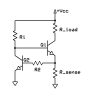
Electric current limiter with NPN transistors
The circuit to the left overcomes the thermal problem (see also, current limiting). To meet how the excursion works, assume the voltage has but been applied at V+. Electric current runs through R1 to the base of Q1, turning it on and causing current to begin to flow through the load into the collector of Q1. This same load electric current so flows out of Q1's emitter and consequently through Rsense to ground. When this current through Rsense to ground is sufficient to cause a voltage drop that is equal to the Vbe drop of Q2, Q2 begins to plow on. As Q2 turns on it pulls more electric current through its collector resistor, R1, which diverts some of the injected current in the base of Q1, causing Q1 to comport less electric current through the load. This creates a negative feedback loop within the circuit, which keeps the voltage at Q1'due south emitter almost exactly equal to the Vbe drop of Q2. Since Q2 is dissipating very niggling ability compared to Q1 (since all the load current goes through Q1, not Q2), Q2 will not heat upwards whatsoever pregnant amount and the reference (electric current setting) voltage across Rsense will remain steady at ≈0.half-dozen V, or one diode drop above basis, regardless of the thermal changes in the 5be drop of Q1. The circuit is still sensitive to changes in the ambience temperature in which the device operates equally the BE voltage drib in Q2 varies slightly with temperature.
Op-amp current sources [edit]
![]()
Figure 7: Typical op-amp electric current source.
The uncomplicated transistor electric current source from Figure iv can be improved by inserting the base-emitter junction of the transistor in the feedback loop of an op-amp (Effigy 7). At present the op-amp increases its output voltage to compensate for the 5Exist drib. The excursion is actually a buffered non-inverting amplifier driven past a abiding input voltage. It keeps up this constant voltage across the constant sense resistor. Every bit a result, the current flowing through the load is constant equally well; information technology is exactly the Zener voltage divided by the sense resistor. The load tin can be connected either in the emitter (Figure 7) or in the collector (Effigy iv) just in both the cases it is floating equally in all the circuits to a higher place. The transistor is not needed if the required electric current doesn't exceed the sourcing power of the op-amp. The article on electric current mirror discusses another example of these so-chosen gain-additional current mirrors.

Figure 8: Constant current source using the LM317 voltage regulator
Voltage regulator electric current sources [edit]
The general negative feedback organisation can be implemented by an IC voltage regulator (LM317 voltage regulator on Figure 8). As with the bare emitter follower and the precise op-amp follower in a higher place, it keeps upwards a constant voltage drop (ane.25 5) across a constant resistor (ane.25 Ω); and so, a constant current (1 A) flows through the resistor and the load. The LED is on when the voltage beyond the load exceeds one.8 5 (the indicator excursion introduces some error). The grounded load is an important advantage of this solution.
Curpistor tubes [edit]
Nitrogen-filled glass tubes with ii electrodes and a calibrated Becquerel (fissions per second) amount of 226Ra offer a constant number of charge carriers per 2nd for conduction, which determines the maximum electric current the tube can pass over a voltage range from 25 to 500 V.[7]
Current and voltage source comparison [edit]
Almost sources of electrical energy (mains electricity, a battery, etc.) are all-time modeled every bit voltage sources. Such sources provide constant voltage, which means that as long as the current drawn from the source is inside the source's capabilities, its output voltage stays constant. An platonic voltage source provides no energy when it is loaded by an open up excursion (i.eastward., an space impedance), only approaches space power and current when the load resistance approaches goose egg (a brusque circuit). Such a theoretical device would have a null ohm output impedance in series with the source. A real-world voltage source has a very low, simply non-nix output impedance: often much less than 1 ohm.
Conversely, a electric current source provides a constant electric current, equally long equally the load connected to the source terminals has sufficiently low impedance. An ideal current source would provide no energy to a short circuit and arroyo infinite energy and voltage as the load resistance approaches infinity (an open circuit). An ideal current source has an infinite output impedance in parallel with the source. A existent-world current source has a very loftier, merely finite output impedance. In the example of transistor current sources, impedances of a few megohms (at low frequencies) are typical.
An ideal current source cannot be connected to an ideal open circuit considering this would create the paradox of running a abiding, non-zip current (from the electric current source) through an element with a defined nix electric current (the open circuit). Likewise, a current source should not be connected to another electric current source if their currents differ but this system is often used (e.thousand., in amplifying stages with dynamic load, CMOS circuits, etc.)
Similarly, an ideal voltage source cannot be connected to an ideal short circuit (R = 0), since this would issue a similar paradox of finite not-zero voltage across an chemical element with defined zero voltage (the curt circuit). Also, a voltage source should not exist connected to another voltage source if their voltages differ but again this arrangement is frequently used (east.g., in common base and differential amplifying stages).
Contrary, current and voltage sources can be connected to each other without any problems, and this technique is widely used in circuitry (e.g., in cascode circuits, differential amplifier stages with common emitter current source, etc.)
Because no ideal sources of either variety exist (all real-world examples have finite and non-zilch source impedance), any electric current source can be considered as a voltage source with the same source impedance and vice versa. These concepts are dealt with by Norton'due south and Thévenin'due south theorems.
Charging of capacitor past abiding current source and by voltage source is dissimilar. Linearity is maintained for abiding current source charging of capacitor with time, whereas voltage source charging of capacitor is exponential with time. This detail property of constant current source helps for proper signal workout with nearly zilch reflection from load.
Encounter likewise [edit]
- Abiding electric current
- Current limiting
- Current loop
- Current mirror
- Current sources and sinks
- Fontana bridge, a compensated electric current source
- Iron-hydrogen resistor
- Saturable reactor
- Voltage-to-current converter
- Welding ability supply, a device used for arc welding, many of which are designed as constant current devices.
- Widlar current source
References [edit]
- ^ Widlar bilateral current source Archived 2011-06-07 at the Wayback Machine
- ^ "AN-1515 A Comprehensive Study of the Howland Current Pump" (PDF) (PDF). Texas Instruments, Inc. 2013.
- ^ Consider the "Deboo" Single-Supply Integrator
- ^ Horowitz, Paul; Winfield Hill (1989). The Art of Electronics, second Ed . UK: Cambridge University Press. pp. 182. ISBN0521370957.
- ^ The value for VBe varies logarithmically with current level: for more particular see diode modelling.
- ^ a b See higher up note on logarithmic current dependence.
- ^ "Tung-Sol: Curpistor, minute current regulator data sheet" (PDF) . Retrieved 26 May 2013.
Further reading [edit]
- "Electric current Sources & Voltage References" Linden T. Harrison; Publ. Elsevier-Newnes 2005; 608-pages; ISBN 0-7506-7752-X
External links [edit]
- Current Sources and Current Mirrors
- FET Constant-Current Source/Limiter - Vishay
- JFET Electric current Source and pSpice Simulation
- Using Current Sources / Sinks / Mirrors In Audio
- Differential Amplifiers and Current Sources

Is There A Voltage Change Accross Of Current Source,
Source: https://en.wikipedia.org/wiki/Current_source
Posted by: smithmoused1964.blogspot.com
0 Response to "Is There A Voltage Change Accross Of Current Source"
Post a Comment